

Sizing Your Personal Space Camera
Launch costs are plummeting thanks to Elon and Bezos burning their well-earned dough on rockets. VC firms are stoked, they’re throwing bills at space start-ups that are even more likely to fail than your typical bathroom finder app. NASA still exists. Given all this, there may soon come a time when you’re customizing your own personal satellites and sending them to space for a bitcoin or two. If that’s something that perks your interest, here’s a comprehensive tutorial on how you’d need to design your satellite to take personalized photos of you from space.
It all starts with image quality, and what part of the spectrum you’re keen on. Lets take a basic example of wanting visible images that have good enough image quality to observe how high your latest ollie is. Or your nollie if that’s the way you swing.
We’ll start with a short introduction to image quality from a camera design perspective. Here are the three main “pillars” and their associated metrics that affect image quality: geometric resolution (GSD), sharpness (MTF), and noise (SNR).
Pillar 1 - Geometric Resolution (GSD)
Geometric resolution is both the simplest of the three pillars to understand as well as the driving contributor to good or bad image quality for space imaging. It is a measure of the size of the object represented by a single pixel in the image, and in the space business we call this Ground Sample Distance (GSD). First order geometry can be used to calculate this, it is related to sensor parameters by Equation 1: GSD / Altitude = Pixel size / Effective Focal Length (EFL) = Instantaneous Field of View (IFOV).


Pillar 2 - Sharpness (MTF)
Even if you have great GSD, it will be hard to discern fine details in your image if it is very blurry. There are many contributors to the sharpness or conversely blurriness of your image. This can be caused by sensor design, manufacturability, imaging and scene conditions, and just plain physics. These effects drive some of the more complex analysis/design/testing activities into the development of a payload. The key metric that is used to capture how much an image will be blurred is the system Modulation Transfer Function (MTF). It essentially tells you how much your image will be blurred (another way to think about it is how much contrast you will lose) vs. different mixes of scene content. The main contributors to MTF are:
- Diffraction - this is inherent in all optical design, basic physics you can’t avoid
- Wavefront error - effects from having mirrors or lenses not perfectly direct the light how you want it, this has to be focused on in great detail when designing and building space cameras
- Image motion – if you move slightly when you take a picture, that picture will be blurrier, we lump these affects into two primary metrics for space: jitter and smear
- Detector affects – the fact that you have a square pixel and are imaging a continuous source with a discrete collector blurs the image
- Atmospheric turbulence – this is one of the main reasons we fly hubble and other space telescopes, the atmosphere blurs an image a good amount
- Obscuration – often times, remote sensing satellites are folded telescopes, so there is some obstruction on the primary mirror from the secondary mirror
- There are many more, but these are the main ones
Pillar 3 - Noise (SNR)
Noise in an image can be caused by how cheap/expensive of a Focal Plane Array (FPA) you have, how much stray light you have prevented in your optical design, what wavelength of light you choose to image, and the heavy hitter - how much light is being reflected off the scene you are imaging. Depending on how much light is being reflected off the scene, you can adjust your exposure time (we call it integration time in space) to achieve better signal to outweigh the noise. But you have to be careful, because increasing your integration time also increases the amount of jitter and smear you will see, which will bring down your MTF. There are many different metrics to use here, but the common one is a simple signal to noise ratio (SNR).
OK, now that we are image quality experts, lets size our personal remote sensor to make sure it can capture, and potentially measure, say for example Clayton's ollie height. We know Clayton’s PR is around 69 cm, and we’ll say we want to be able to track that to about 1 cm resolution. To be able to resolve that 1 cm difference if Clayton ends up throwing a 70 cm ollie, we’d need a GSD of around 1 cm. The variables we can play with there are given by equation (1): focal length, pixel size, and altitude. Low altitude, large focal length, and small pixel size all play in our favor for a small GSD. Typically you can’t go lower than 6-8 um for a pixel on an FPA for space imaging, due to SNR needs (although your iPhone camera has a tiny 1.5 um pixel). It’s also very hard to fly lower than say a 300 km altitude due to the atmosphere causing drag on the satellite. And while there’s no real limitations on focal length, the longer focal length means a more complex folded telescope with hella mirrors and if you can’t compensate for that with a larger telescope diameter then you’re F/# (pronounced “F-number”, and in the photography world, “aperture”) could get ridiculously large and decrease your SNR and MTF a lot (SNR and MTF are generally better with lower F/#).
I tried to stop the F/# discussion here in my first draft, but it just didn’t seem right since it is pretty essential to this first order sizing. F/# is defined as EFL/D, where D is the pupil diameter. For space based optical systems, you can almost always use the diameter of the telescope for D, since it is most often the thing that limits the size of the light beam (aka “pupil”). But for some cases, there may be some “stop” in the system that limits the pupil size or can be adjusted to limit that size, and as a result your F/# will change. For example, most consumer cameras have F/#’s that are adjustable, going as low as like F/1.2 (I’m quoting Brittney Griffin here, see her dope content at https://www.brittanydawnphotography.com/ ), but keep in mind if you have a camera that can go that low you have serious clout in the photography world. But in the space world, if you brought up the idea of doing anything to limit the pupil size more than necessary, you would be ridiculed and maybe fired. The general rule of thumb for space telescopes is that mass and cost increases exponentially as you increase the telescope diameter, so you’re going to go great lengths to get more and more of that pupil light. Earth imaging satellites typically fall somewhere within a static F/7 to F/25 depending on how limited you are by GSD and altitude. But if you’re thing is terrestrial photography, you’d sometimes want a very low F/# in order to put closer objects into pristine focus – e.g. the new apple phones portrait mode.
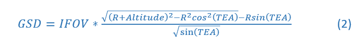
Back to sizing the focal length, there’s one caveat. If we’re trying to look at Clayton’s ollie, we’re going to have to image him at an angle (referred to as “off-nadir”) so we can see under him instead of looking straight down at the earth (“nadir”). That’s gonna increase our object distance, so we can’t just use altitude in the equation. There’s some pretty complex formulas for off-nadir distance, since the GSD is going to distort in funky ways in the X and Y direction and you have to take into account the curvature of the earth, so I won’t explain equation (2) below but just trust me. The numerator of the equation is how you calculate slant range for a given elevation angle (TEA, target elevation angle). We know our best bet is a 6 um pixel and a 300 km altitude, and we’ll assume that a 60 degree target elevation angle will give us a good view of the ollie. Implementing those values into the equations, we arrive at a 369 km slant range and a 220 meter effective focal length to get that +/- 1 cm resolution we need (TEA in the equation corresponds to epsilon in the figure). These are all real numbers.

We now have our 1 cm GSD on lock, but we have to make sure we can still make out the image and that it’s not too blurry (MTF) or noisy (SNR). But rather than getting into the gritty details of everything we need to consider for those two pieces, I’m gonna bet on fam that when the time comes to design this thing everyone will be ready. So we’ll just do first order sizing and use a concept dating back to George Eastman’s days that tells us some info about how MTF and SNR will play out. That concept is referred to as “optical Q.”
Q is an incredible metric when doing architecture/high level design studies, it tells you so much about your system and gives you the best snapshot about what kind of pictures it will take. People love trading Q, arguing about what Q you should design, claiming you have to use the same Q as heritage, etc. By definition, it is the ratio of the system’s Nyquist frequency (determined by pixel size, p) and the optical cut-off frequency (determined by F/# and the average wavelength of light that you are imaging, l).

For imaging missions, it is very favorable to design Q to some value in between 1 and 2. This is the range that trades typically happen, and you’d be surprised how significant the difference between a Q=1.42 vs. Q=1.69 image is. For our purposes, we can infer from Equation (3) that a higher Q for our set altitude will give you better GSD. However, as Q increases, MTF and SNR decrease (see reference 2 for deets). Since we already have our GSD set, and our focal length is pretty outrageous, lets figure out what aperture diameter gets us at least below 2 and call it done (as you go above 2, images start getting really blurry). Our system won’t get quite as great MTF and SNR if we went with Q closer to 1, but Clayton usually doesn’t skate at night and gets lots of hang-time at the top of his ollie so we should be in good shape. Using 0.55 um as lambda since that is the mean wavelength of visible light, we can plug in our other parameters and set D = lambda*EFL / pixel size*Q = .55um*220m / 6um*2 = 10 meters.

10 meters! For the diameter of the telescope. Not small. But maybe worth it if launch costs come down. Probably worth it. Only about 30% larger than the largest space telescope NASA has developed which is 5 years behind schedule and only estimated to run us tax-payers about $8.6 billion.
Further readings if you’re interested:
[1] NASA James Webb telescope:
[2] Deep dive into image quality and optical Q by one of the image quality legends:
Homework:
What is the F/# of the system we designed?


